Requirements
-
Deflection of the gears cannot exceed 0.005 inches.
-
The plate needs to hold gears revolving at 2.5 rpm.
-
The plate needs to withstand the crushing load of 10,500 lbs.
-
Feed rate needs to operate at 1 foot per minute.
_JPG.jpg)
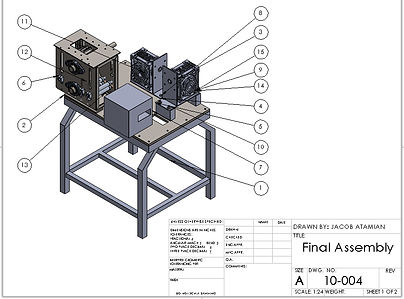
Figure 3: Final Assembly
Analysis
The project was directed towards creating a more rigid system of gears and motors. The first analysis conducted displacement tests to determine where the system was moving at locations across the crushing housing and gear boxes. Testing resulted in a base plate design to stabilize all moving components. Table dimensions were taken for plate design 26"X36".
(Appendix A1-A2)
An initial plate deflection analysis was conducted with a square cutout in the top left section of the plate. This plate analysis had smaller dimensions than the final plate design of 21"x29" based on a different design that would later be changed.
(Appendix A3)
A plate redesign was made to make the manufacturing process easier and more logical. Deflection analysis was conducted with a max deflection value of 0.005 inches. Calculations require a 3/4 inch plate made of ASTM A36 hot rolled steel.
(Appendix A6)
Further testing was conducted to determine the added load of the crushing gears to the plate (467 lbs). To fit the maximum deflection requirement of 0.005 inches, a truss was designed to support this load underneath the plate. Truss geometry was determined from supporting table dimensions. Euler's column buckling analysis was conducted to determine a sufficient square tubing for truss members (1/2"x1/2"x0.049" ASTM A513).
(Appendix A4-5, A7, A9)
An analysis was conducted to ensure the bolts and locating pins used in the assembly would not shear under operation. Calculated design factors were well above the standard value of N=2 meaning they will not shear under system conditions.
(Appendix A8, A10)
A finite element analysis was done on the base plate using Inventor Nastran (Figure 4). This analysis determined the maximum displacement of the plate to be 0.00333 inches as a reaction to the load from the crushing gears. This resulted in 8.7% error from the calculated displacement of 0.00365 inches. A safety factor of 1.4 from displacement allowed for the truss design to be scrapped. The plate does not need the extra support.
(Appendix A11)

Figure 4: FEA of Base Plate Displacement
Physical measurements needed to be taken of parts previously manufactured for the assembly. The measurements needed to be taken due to inaccurate drawings provided by previous project members. Modifications needed to be made to housing spacers to incorporate them into the new assembly.
(Appendix A12)
A final finite element analysis was conducted to determine if any significant side plate deflection would occur in the existing crushing housing assembly. A Nastran model confirmed the side plate would absorb the load from the crushing gears. The stress of 5082 psi was well below the yield of ASTM A36 Steel. Maximum deflection was well below the requirement at 0.0005 inches as shown in Figure 5.
(Appendix A13)
