Deconstruction
The first stage of the construction process was to deconstruct the previous assembly to make way for new parts. The angle irons that previously provided support to the components were removed.
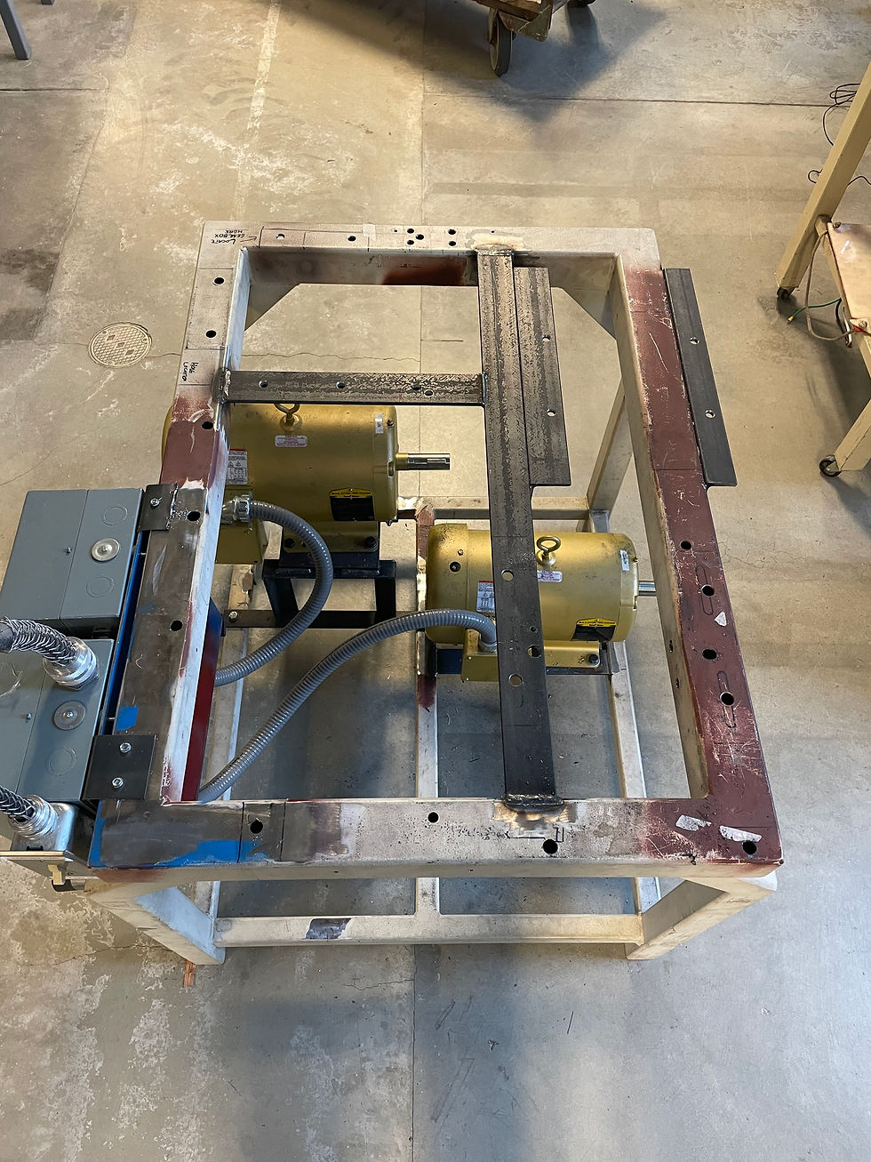


Gallery 1: Deconstruction of Supporting Table
Existing Part Modifications


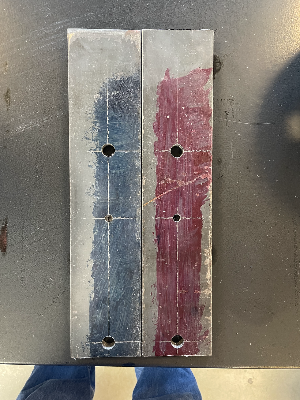
The next tasks were to modify some of the existing parts of the assembly while waiting for material to arrive. The aluminum housing spacers, parts 20-013 and 20-014, needed to be modified by drilling 1/2" pin holes to locate Gearbox #1 on the base plate. A knee mill was used to accomplish these modifications. The height of the spacer closest to the output shaft needed to be shaved by a quarter of an inch to be level with all other components in the assembly. This was done using a bandsaw and 1/2" end mill. The pin hole for part 20-014 was not aligned with the pin hole drilled into part 20-002. This required a 1/2" end mill to extend the hole to align with the pin. The spacers were milled to a final height of 3.79 inches to bring the output shaft of Gearbox #1 concentric with the input shaft of Gearbox #2.
Gallery 2: Gearbox #1 Housing Spacers
The supporting table was modified with 17/32" holes to mount the plate. To place holes accurately, the plate was placed on the table and aligned with its existing component holes. Edge holes were hand drilled when proper alignment was achieved. Some issues became evident in the placement of the component holes for Gearbox #2. Because the component was shifted to align properly with Gearbox#1, there arose a new misalignment with the existing holes in the table. An angle grinder was used to extend the hole through the edge of the table to allow clearance for the fasteners. Larger washers were used to keep the bolt secure through the table to Gearbox #2.
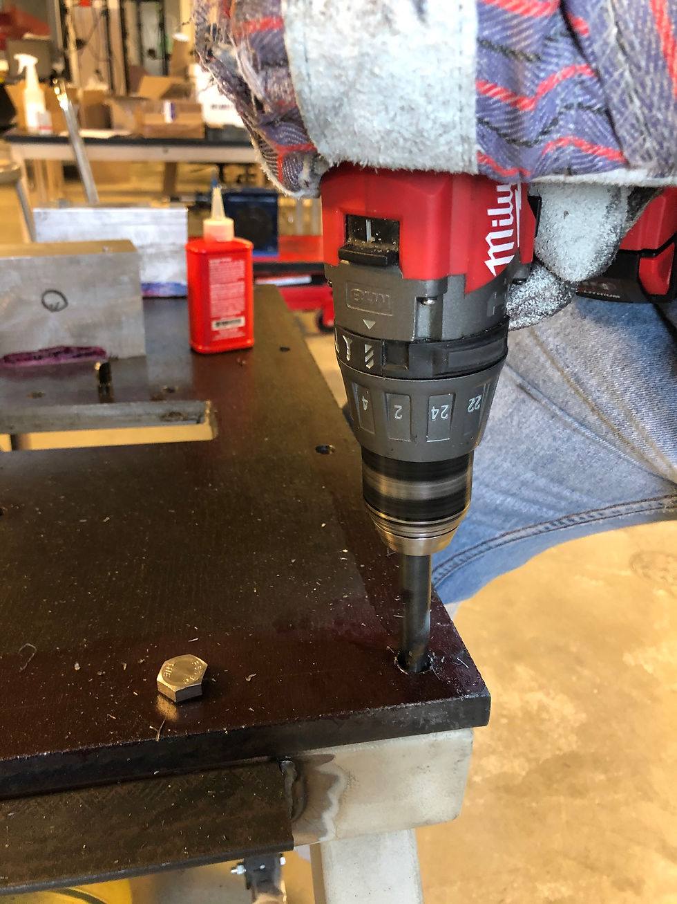


Gallery 3: Mount Holes For Supporting Table
Part 20-002: Base Plate
Part 20-002 was manufactured using a knee mill. The first step taken in this process was to hole punch all hole locations. The next step was to drill all through holes. The plate needed to be continuously adjusted and remounted to the mill table due to it's large size. A hydraulic lift table was used to support the hanging area of the plate when adjusted for edge holes, shown in Figure 6. The other end of the plate was clamped with c-clamps where the table had room. Through holes drilled were a size 17/32" to allow for clearance of 1/2-20 Bolts. Two holes for the placement of Gearbox #2 needed to be re-drilled due to incorrect placement. The next holes to be drilled were the bottomed holes for the pins. These were drilled with a 7/16" bit to a depth of 0.60 inches.
The final process for this part was milling out the square hole for the chain access to Gearbox #1. This process is shown in the video below. Spacers were placed beneath the plate to allow for a 1/2" end mill to cut through the bottom of the plate and not run into the table. The plate was mounted to the table with c-clamps at the ends and a bolt fastened securely through one of the through holes to the mill's table. The size of the slot was 2" x 6".
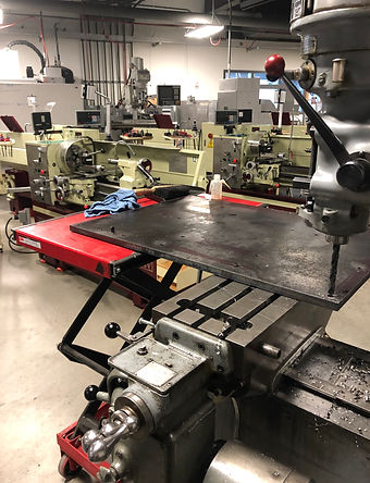
Figure 6: Manufacturing Part 20-002

Figure 7: Completed Part 20-002
Part 20-011: Crushing Housing Spacers
Half-inch housing spacers were placed between the base plate and crushing housing to allow clearance for the driving spur gears and crushing wheels. Locating pins were placed on the spacers to locate the crushing housing. These parts were manufactured on a mill. Gallery 4 shows the finished parts and incorporation into the final assembly with clearance.